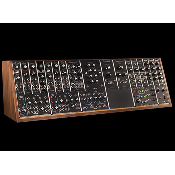
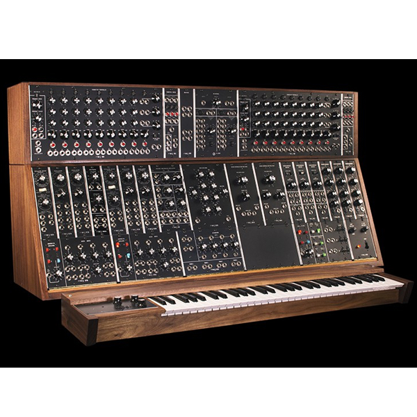
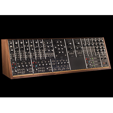
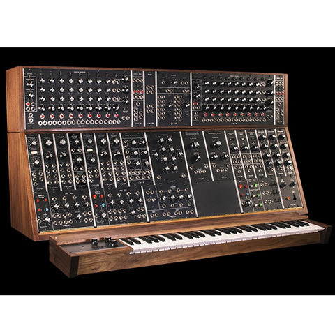
The Moog System 35 modular synthesizer is a well-refined 5-oscillator instrument comprised of 22 handcrafted analog modules and housed in a hand-finished solid walnut cabinet. This elegant studio solution has been faithfully recreated to be the centerpiece of inspiration and sound in the modern composition studio, and delivers all of the sonic depth and dimension found only in a vintage Moog modular synthesizer. Also available configured with an additional 960 Sequencer Complement B.
Faithfully Recreating The System 35
Three years of research and design has culminated in Moog Music recommencing the manufacturing of a limited number of Moog System 35 modular synthesizers. Using all of the original documentation, as well as the original circuit board and art files, Moog engineers have hand-built true recreations of the original instruments based on their 1973 factory specifications.
Each individual module is hand-stuffed and the components are hand-soldered to circuit boards using traditional wiring methods. Each module is then finished with a photo-etched aluminum panel, and placed in its new modular instrument.
This limited reissue of the Moog System 35 modular synthesizer is built to order. Only 35 total units will be made and sold worldwide.
System 35 Modules
3x 902 Voltage Controlled Amplifiers
1x 904A Voltage Controlled Low Pass Filter
1x 904B Voltage Controlled High Pass Filter
1x 907A Fixed Filter Bank:
3x 911 Envelope Generators:
1x 921 Voltage Controlled Oscillator:
2x 921A Oscillator drivers:
4x 921B Oscillators:
1x 923 Random Noise/Filter:
2x CP3A Console Panels:
1x CP4A Console Panel:
1x CP8A Console Panel:
1x CP35 Console Panel:
1x 180 Watt 120 VAC or 230 VAC Switch Selectable Power Supply
Included Patch Cabling
10x - 1' 1/4" TS cables
8x - 2' 1/4" TS cables
8x - 3' 1/4" TS cables
4x - 4' 1/4" TS cables
2x - 5' 1/4" TS cables
2x - 1' S-Trigger cables
2x - 3' S-Trigger cable
1x - 'Y-cable'S-Trigger
Weight and Dimensions
Main Cabinet
Weight: 100 lbs
Dimension: 48 ½” wide x 15 ½” high x 14” deep
Modules And Their Original “Functional Descriptions”.
902 Voltage Controlled Amplifier: The 902 voltage Controlled Amplifier is a differential input and output circuit which gives an overall voltage gain of 2 {6dB} when the manual control potentiometer is at maximum {6}, or when a control voltage of 6 volts is applied to the control input. Maximum sum of control voltage {fixed control voltage and input jacks} is approximately 7.5 control volts, producing +4.7dB or gain of 3. Two modes of gain response are available: linear and exponential.
904A Voltage Controlled Low Pass Filter: The 904A Low Pass Filter attenuates frequencies above the fixed control voltage cutoff point at a rate of 24dB per octave. The cutoff point {cutoff frequency} is voltage controlled through the control input jacks. The sum of the applied control voltages doubles the frequency of the cutoff point for each one-volt increase {volt per octave standardization}. The regeneration potentiometer {variable Q} varies the amount of internal feedback, creating a resonant peak at the cutoff frequency. This resonant peak will break into oscillation at clockwise settings of the regeneration pot, creating a voltage controlled sine wave generator. The fixed control voltage pot covers a 12-volt {octave} range. The overall range of the FCV pot is determined by the Frequency Range switch, which moves the frequency cutoff range in two-octave steps.
The basic cutoff frequency of the Low Pass Filter is determined by the combination of fixed control voltage and frequency range in addition to the control input signals. An increase in regeneration narrows and increases the strength of the cutoff frequency peak, while decreasing the amplitude of the lower frequencies.
904B Voltage Controlled High Pass Filter: The 904B Voltage Controlled High Pass Filter attenuates input signal frequencies below its nominal cutoff frequency setting. The attenuation below FCV cutoff setting is 24dB/oct. As the fundamental is generally the loudest frequency component of a complex tone, deletion of the lowest frequency range can radically alter the timbre. The FCV cutoff point is raised or lowered in octave per volt control inputs.
The Frequency Range switch sets the overall range of frequencies covered by the Fixed Control Voltage potentiometer. The Low range encompasses 4hz to 20kHz, while the High range shifts 1 1/2 octaves up to 10Hz through 50kHz.
907A Fixed Filter Bank: The 907A Fixed Filter Bank is a non-voltage controlled modifier, which emphasizes or reduces the gain of the center frequency bands indicated on each of the eight center pots, in addition to the cutoff points set by low pass and high pass filters at either frequency extreme. A total of 10 overlapping LC networks are included.
911 Envelope Generators: At the introduction of a switch-to-ground {S-trigger} trigger signal from an external source, the 911 Envelope Generator produces a single voltage contour whose time/voltage variation is determined by potentiometers T1, T2, T3 and a time constant sustaining level pot {Esus}. Closure of the input trigger switch directs the voltage contour to T3 {final decay} regardless of what stage { T1, T2 or E} was in current operation. The Envelope Generator requires an S-trigger to operate. External sources must be converted to the S-trigger format.
921 Voltage Controlled Oscillator: The 921 Voltage Controlled Oscillator is a variable waveform generator, which produces frequencies ranging from .01Hz to 40kHz. Four waveforms are available: Sine, Triangular, Sawtooth, and Rectangular {with variable duty cycle}. Both fixed and variable levels can be obtained from front panel output jacks. Nominal frequency is set manually by the scale, coarse range, frequency and {octave} range controls found at the top of the module. Voltage controlled rectangular width is set by the knob in the upper center {left}, with accompanying voltage input jacks. Clamping point {waveform reset control} may be set with the lower left knob and accompanying trigger inputs to the left. Multiple frequency control inputs can be plugged into this module in parallel. All waveform outputs can be used concurrently if desired.
All manual controls on this module can be moved or switched during operation. This module functions as both an audio or control voltage generator.
921A Oscillator drivers: The 921A Oscillator Driver is a control voltage processor, which drives associated 921B oscillators through internally wired connections {via edge connectors}. Two voltages are generated: one for frequency control and one for rectangular wave duty cycle. Control inputs to this module change the frequency of its associated oscillators in volt/octave increments. Manual adjustment to the Frequency and Width Of Rectangular Wave pots changes the nominal frequency and duty cycle of all connected 921B's in parallel. Two ranges are provided on the Frequency potentiometer: semitone {two octaves compass} and octave {12 octaves compass} These ranges are selected by the white switch below the Frequency potentiometer. Control inputs for frequency and rectangular width are summing.
921B Oscillators: The 921B Oscillator generates frequencies from 1Hz to 40kHz minimum. They are wired in groups to a common 921A Oscillator Driver, which provides both exponential frequency control and rectangular width voltage control.
Like the 921 Oscillator, this is one of the building blocks of analog synthesis. This oscillator generates both sub-audio and audio frequencies for control and audio signal use. The Frequency pot at the top of the module has a two-octave range for fine-tuning, while the Range switch shifts the frequency of the oscillator in octaves, up or down. Number indications on the Range switch correspond to traditional organ pipe range notations. Fixed level outputs for Sine, Triangle, Sawtooth and Rectangular waveforms are found at the right of the modules. DC Modulate is a linear frequency control input {does not conform to 1 volt/octave control voltage format}. AC Modulate input is a capacitor-coupled circuit like the DC Modulate input, however, blocking constant DC voltages.
921B Oscillators may be phase locked together via the Synch input jack and the associated three position Synch Switch. Phase locking capability is generally limited to the first six harmonics of the input signal. A sawtooth waveform is recommended for best synchronization results.
923 Random Noise/Filter: The White and Pink noise outputs of the 923 Random Noise/Filter module produces continuous bursts of random frequencies and waveshape throughout the audio spectrum. Pink noise displays equal amplitude/energy per octave. A resultant lower frequency concentration for Pink Noise marks the difference between the two outputs, with white noise appearing in even intensity throughout the audio spectrum. Parallel outputs are provided for both noise sources. The two manual sweep filters, Low Pass and High Pass, are single pole {RC} circuits with a frequency cutoff slope of 6dB per octave.
CP3A Console Panels: The CP3A module has four varied functions. The primary circuit is a 4x1 mixer with positive and negative outputs and a maximum gain of 2x. This mixer can combine both AC and/or DC voltages. The second series of functions are four signal routing switches, which connect the incoming control voltages from keyboard, ribbon or other controller units to the frequency control input of associated oscillator drivers found directly above the switching panel. The fourth input switch has both an external input jack and attenuator {found directly below}. This input jack is connected to the Oscillator Driver when the associated switch is on and the attenuator set above zero. At "10" a signal introduced here will be equal to one which is introduced directly into the frequency control inputs found on the Oscillator Driver itself. The two final elements found on the CP3A are a multiple {signal splitting - one input becomes three} and trunk line jacks, which carry a signal to the rear of the synthesizer.